Introduction:
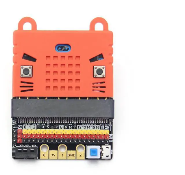
This is a low-cost expansion board for Micro:bit, which is specifically used for the IO ports of Micro:bit. It has taken all the IO resources on the Micro:bit, and also has a buzzer on the board. It is connected to the P0 pin through the jumper cap. The P0 pin can be released using a jumper cap. The small size is very suitable for small projects using Micro:bit.
Product parameters: Length x width x height: 57mmx44mmx12mm
Technical parameters:
Power supply mode: IobitV.2.0 supports USB5V power supply. This power supply mode requires pressing the blue power switch.
Working voltage: 3V-5V (5V sensor module is not supported under 3V power supply)
Output current: 3V and 5V power interface with maximum output 1A
Serial port extraction: serial port can map IO port
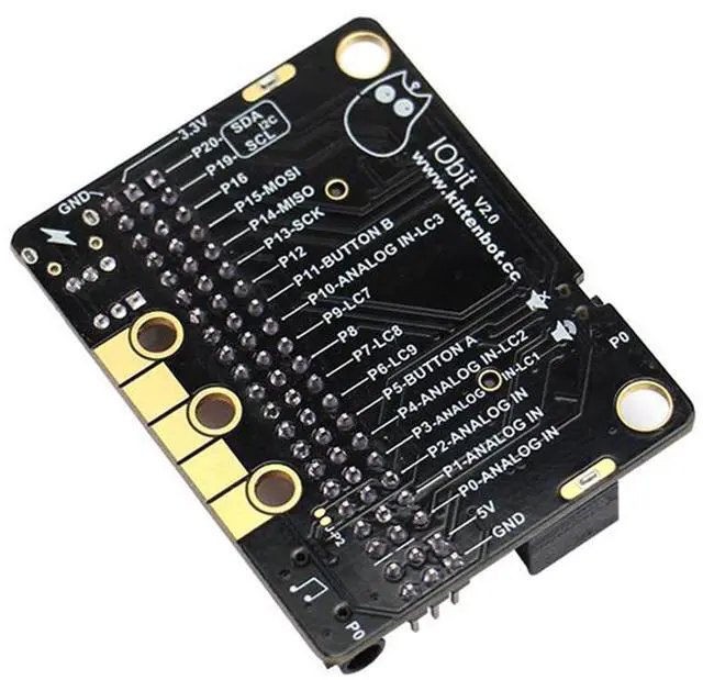
I2C port leads: pins 19 and 20 can only be used as I2C function pins. They cannot be read and written as ordinary IO ports, because Micro:bit bottom is dead.
Spi port leads; 14, 15 (IO port can be read and written).
Programming:
MakeCode/KittenBlock (based on Scratch3.0) with hardware: Micro:bit.
With common building blocks -> pin
Before using the building blocks, you must first understand the control method or reading method of the electronic module you are using.
Digital reading
Most newbies will fall out of here because they often ignore setup pull-ups or pull-downs during initialization. So the level state will fail after reading it once. Therefore, we must pay attention to this. Micro:bit itself does not help to set up and down by default, you need to set it yourself.
Analog reading
In response to the analog reading, because the analog reading will return a value of 0-1023, it is always inconvenient to display it with a dot matrix screen. So here we take advantage of the unique serial port debugging function of the MakeCode offline version produced by Xiaoyan. First, download the program shown in the figure to open the serial port. In step 2, the console of the device will appear, you can see the data returned in real time.
Digital writing
Digital read here does not need to set up and down.
Analog write
Simulated writing an example of a flashing light.
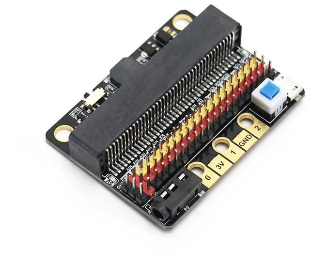
Introduction to IObit hardware:
5V power
Insert the USB power supply (5V 1A) as shown in Figure 1. Press the blue button at 2, and the red indicator light at 3 will light up. You can use the left 5V interface.
P0 buzzer
Toggle switch to turn off the buzzer function (see the silk screen on the back of the board for status)
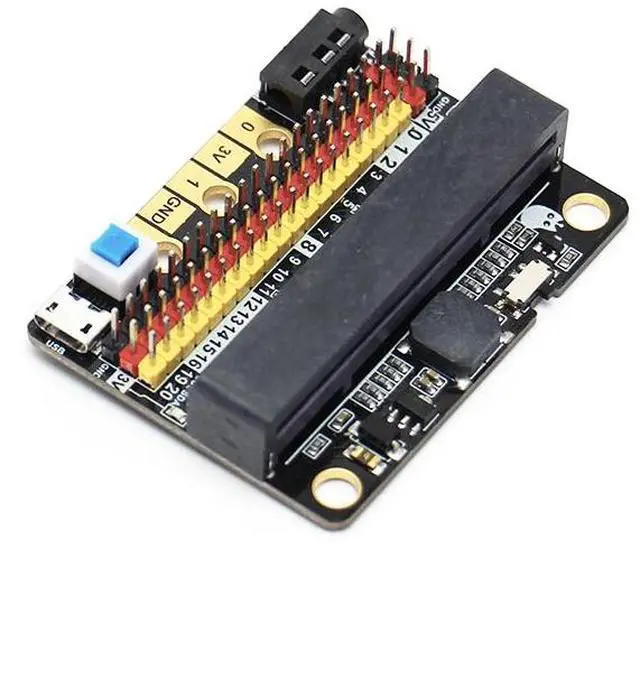
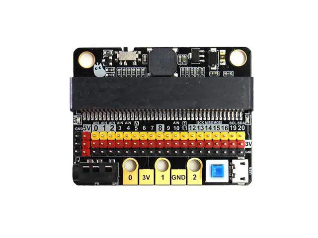
3Pin IO port leads:
All the pins in the Micro:bit have been taken out without any reservation (Note: there are no P17 and P18 on the Micro:bit, it’s not that the IObit is not taken out)
Yellow corresponds to the different IO pins
Red corresponds to 3.3V/5V (with silkscreen)
Black corresponds to GND
5PIN gold fingers
The gold fingers of the Micro:bit are used to draw 3v, gnd, P1, P2, and P3 respectively. This is for users who prefer to use alligator clips
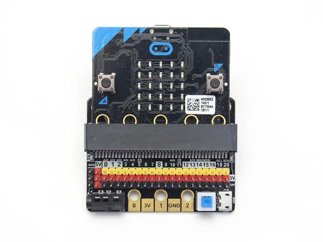
40P Micro:bit horizontal socket
Compact size socket
Board mounting holes and fixing
The two outermost holes are approximately 4.8 mm in diameter and are compatible with Lego friction pins with a spacing of 48 mm.
IObit programming use:
If you haven’t gotten started with Micro:bit, first get started with Micro:bit, this is the operating premise.
If you use the high-low read function of the pin, you must set the pull-down on the pin.
If P0 is used as a normal IO port, the buzzer toggle switch must be turned off, otherwise the buzzer will sound or the IO read value will be abnormal.
Use the shared pin with the Micro:bit dot matrix (such as 3, 4, 5, 6, 7, 8, 9, 10, 11), remember to disable the dot matrix screen on the software, otherwise it will be a bit of a screen burst.
The USB port allows a maximum input current of 1A.
Do not place it on a metal surface to avoid short circuit.